Description
Applications
|
Features and Benefits
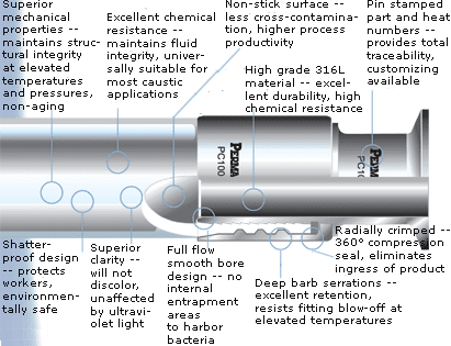
| Ultra-Pure |
|
| Non-Stick Surface |
|
| Superior Visual Clarity |
|
| Radial Crimp Design |
|
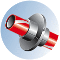
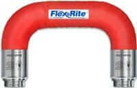
Flow Indicator Details
|
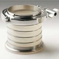
End Connector Styles
 |
Flow Indicator Specifications
| Hose Specifications | ||||||
| Part Number |
Size (in.) |
Inside Diameter (in.) |
Outside Diameter (in.) |
Wall Thickness |
Pressure (PSI) (p.s.i.) @ 70° F |
Burst Pressure 70° F |
| CFI050 | 1/2 | 0.500 | 0.700 | 0.100 | 200 | 800 |
| CFI075 | 3/4 | 0.750 | 0.950 | 0.100 | 175 | 700 |
| CFI100 | 1 | 1.000 | 1.250 | 0.125 | 125 | 500 |
| CFI150 | 1-1/2 | 1.356 | 1.610 | 0.125 | 105 | 420 |
| CFI200 | 2 | 1.856 | 2.100 | 0.125 | 72 | 290 |
| CFI250 | 2-1/2 | 2.356 | 2.650 | 0.150 | 50 | 200 |
| CFI300 | 3 | 2.856 | 3.230 | 0.185 | 40 | 160 |
| CFI400 | 4 | 3.856 | 4.276 | 0.210 | 30 | 120 |
Note: Burst pressure ratings at ambient 70°F (21°C). For applications over 300°F, consult factory.
| Pressure Correction Factors for All Non-Caged Flow Indicators | ||||
| Using operating pressure @ ambient with correction factors for elevated temperatures. | ||||
| 70°F | 150°F | 200°F | 250°F | 300°F |
| 100% | 65% | 50% | 35% | 25% |
Example: 1″ flow indicator @ 200°F rated @ 125 P.S.I. ambient x .50 = 62.5 P.S.I. @ 200°F.


